Optics and Opto-Electronics Laboratory
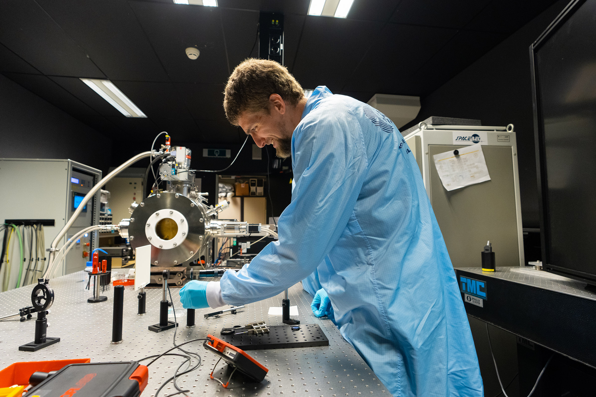
The Optics and Opto-Electronics Laboratory (OOEL) is a joint laboratory of the Optics (TEC-MMO) and Opto-Electroncis (TEC-MME) sections at ESTEC
The OOEL provides expert advice with a state-of-the-art laboratory to:
- Evaluate promising novel technologies prior to industrial activities
- Independently assess the outcome of industrial activities in support to ESA’s projects and Research & Development efforts
- Experimentally support root-cause-analysis for system or component level malfunctions
- Maintain hands-on experience and competence of staff and trainees (Young Graduate Trainees and interns)
For testing requests, access to lab facilities, training and consultancy services, please refer to:

OOEL provides services in the following domains:
OOEL provides services in the following domains:
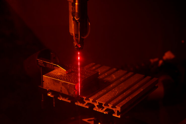
Laser-induced contamination mitigation
Laser-induced damage testing
Laser diode characterisation
CCD & CMOS detector validation
Tailored laser-based measurements
Stray light (angle-resolved scatterometry and BSDF) with data analysis
High-resolution spectral transmittance and reflectance (200 to 2500 nm)
Surface form and wavefront error (@633 nm)
Microscopic surface topography and 2d roughness profilometry (white light interferometry)
Solar simulator absolute irradiance radiometry
Spectral and Radiometric calibration
Optical communication link emulation (scintillation and tip-tilt jitter) in fiber and free space
Related fields of interest
Related fields of interest for the laboratory include fibre and free-space optical communication links as well as fibre optic sensor networks serving as a satellite's nervous system, optical multiplexing techniques, advanced detectors and arrays and the effects of the space environment on opto-electronic devices.
Lab Overview
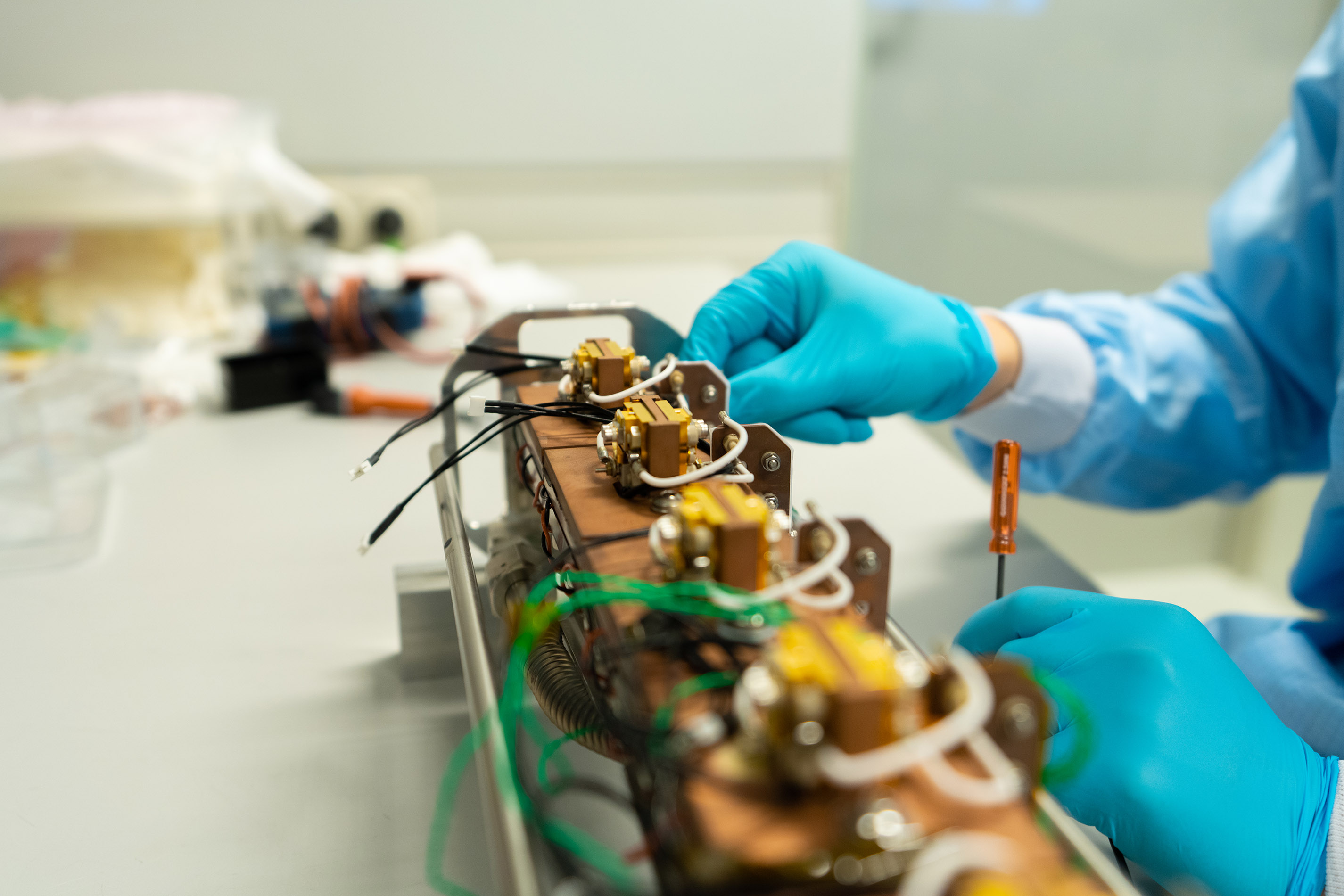
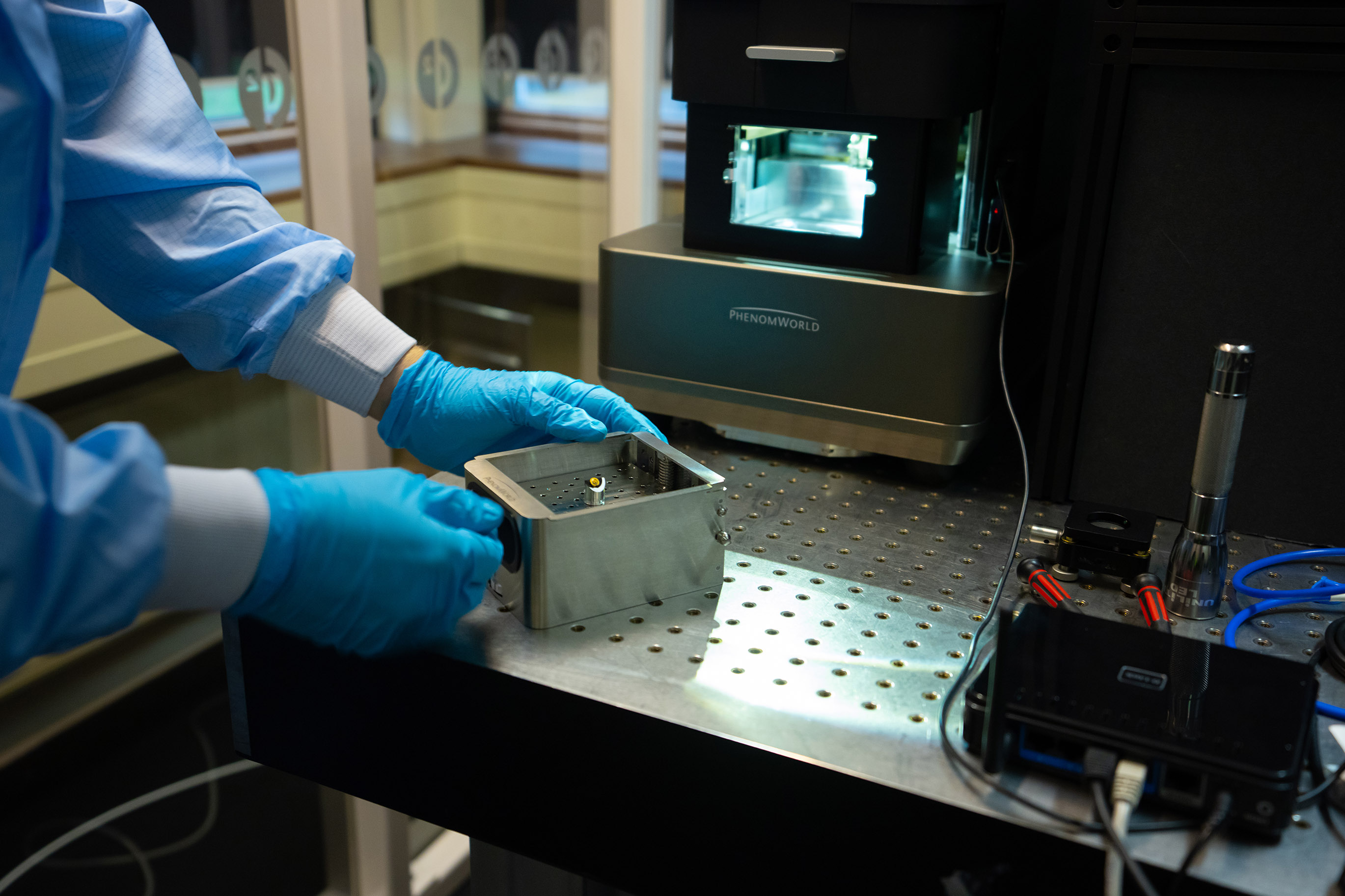
The laboratory's current emphasis is on characterising and/or calibrating detectors and small cameras, optical components, laser beams and other optical signals. Capabilities in testing and characterising optical and quantum communication links and technologies are being developed.
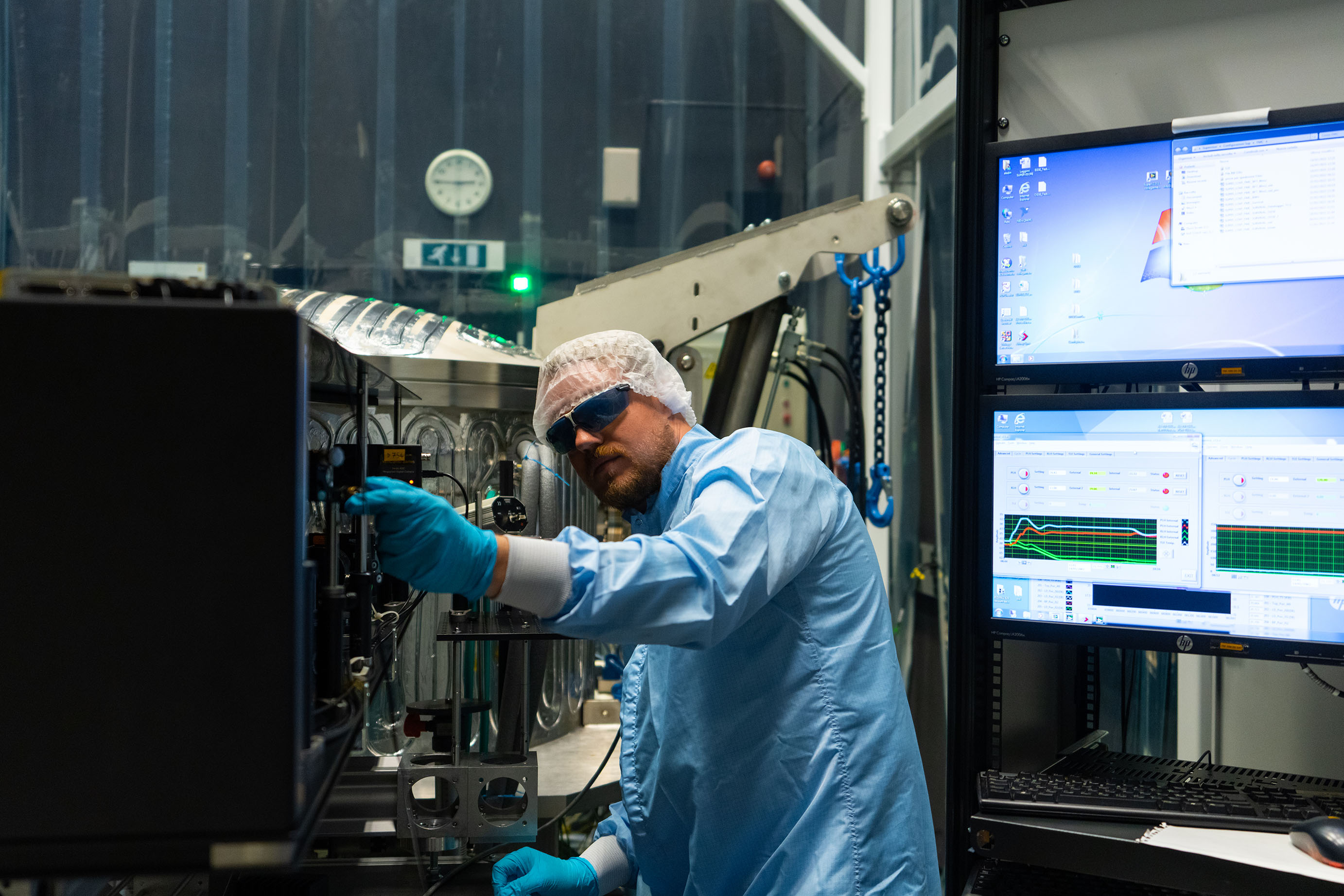
It includes a Class 10,000 (ISO 7) cleanroom, two fully equipped optoelectronics laboratories designed for the operation of Class 4 laser systems (defined as powerful enough to burn skin, cause permanent eye damage or ignite flammable material), workshop and storage rooms.
It has the equipment necessary to measure the optical spectrum, beam profile, power and energy, stability and modulation response, in free space as well as optical fibres.
services
Testing
- Test Infrastructure
- Performance Evaluation
- Qualification-tests & Validation tests
- Test Beds Development
- Test methods development
- Life testing
- Environmental testing (for instance Thermal Cycling Tests, Thermal Vacuum Test, etc)
- Anomaly investigations
- Characterisation
Measurements
- Prototyping
- Advanced Metrology
- SEM
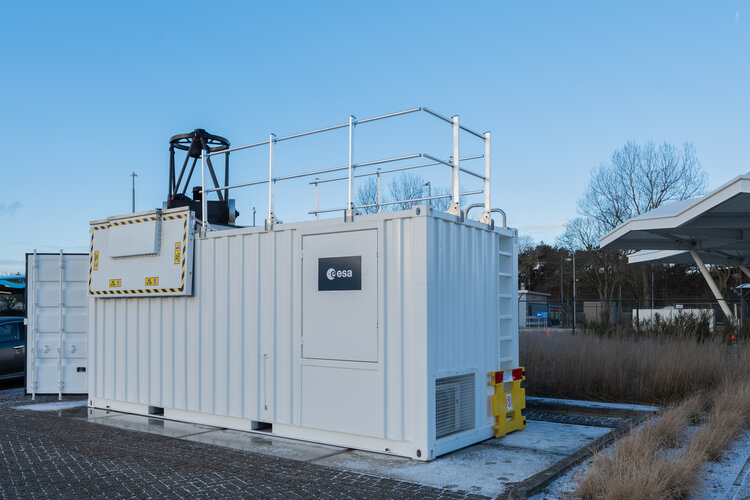
- Atmospheric LIDAR (Mobile)
- OTDR
- Wavemeter
- Optical Spectrum Analysis
- 2D Transmission
- Laser Characterisation
- SWIR and VIS Detector Characterisation
- LIC and LIDT Measurement
Simulation
- BER simulations of optical links
- Optical communication link evolution (including spacecraft trajectory, ground station passes, intersatellite links, pointing error rejection, scintillation, optical link budget, etc.)
Analysis
- Laser and detector characterisation measurement
Other Tests
- Detectors electro-optical testing
- Detectors spectral responsivity
- Laser induced contamination
- Laser induced damage
- Long term high power diode lasers testing
- Laser diode accelerated lifetime testing
- Radiometric calibration
- Scatterometer
- Interferometry
Technical Expertise
- Consultancy
- Training
- Development of Space Standards
SIMPLIFIED ACCESS TO LABS
- External Parties Can Visit the OOEL under the Rules of Visiting ESTEC, (the Use of Equipment Requires Training and Supervision by ESA Staff)
WE CAN HELP YOU GET THE BEST OUT OF OUR LABORATORIES
REQUEST ACCESS TO THE LAB
TO GET ACCESS TO THE LAB, MAKE A REQUEST VIA EMAIL


