Antenna Laboratory
At ESTEC, ESA operates some of the largest European test facilities dedicated (but not limited) to the testing of space hardware. Among these is the Antenna Laboratory
The Antenna Laboratory, through its several facilities and with over 30 years of existence, provides state-of-the-art measurement services to ESA projects and external customers and explores and develops new measurement techniques.
The Antenna Laboratory provides testing capabilities for antennas and payloads, including radiation pattern measurement, absolute gain, phase centre determination, group delay and any other end-to-end payload- or platform-radiated signal across a frequency range between a few hundred MHz to 5 THz. Some of these capabilities are available under various environmental conditions, in order to verify antenna and radiated payload performance in flight conditions.
The Antenna Laboratory provides support to both ESA projects and external customers – including small- to medium-sized companies lacking access to comparable private-sector facilities – needing to assess new antenna designs and techniques and to qualify designs for flight. These have included some of ESA’s largest flight hardware.
 +
+Reflectivity measurement
 +
+Sample measurement in the Microwave Material RF characterisation free space test facility
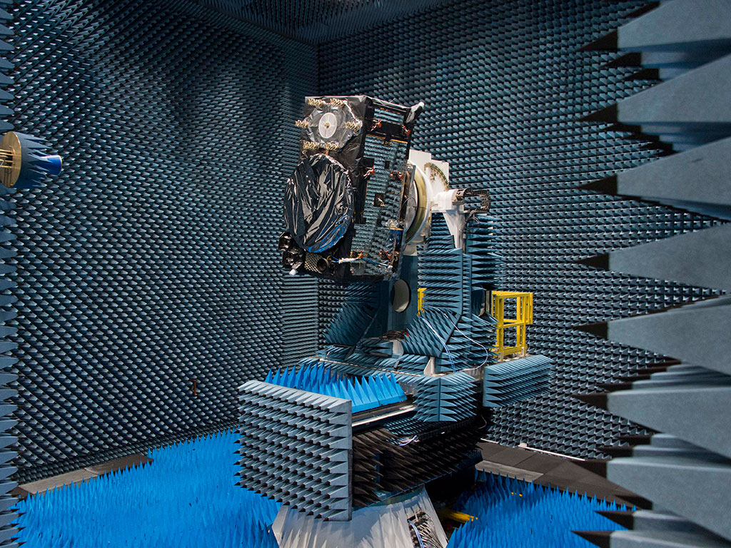 +
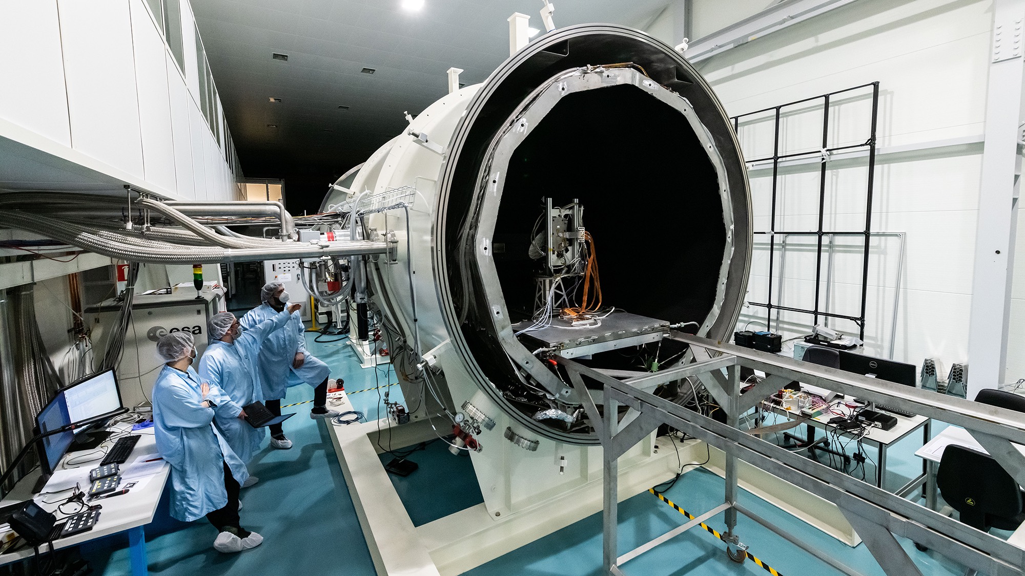
+Satellite inside HERTZ
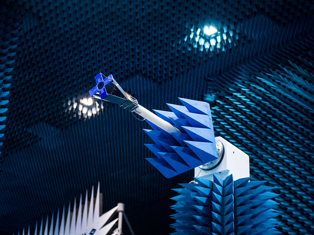 +
+Qarman CubeSat in Hertz test chamber
 +
+LORENTZ
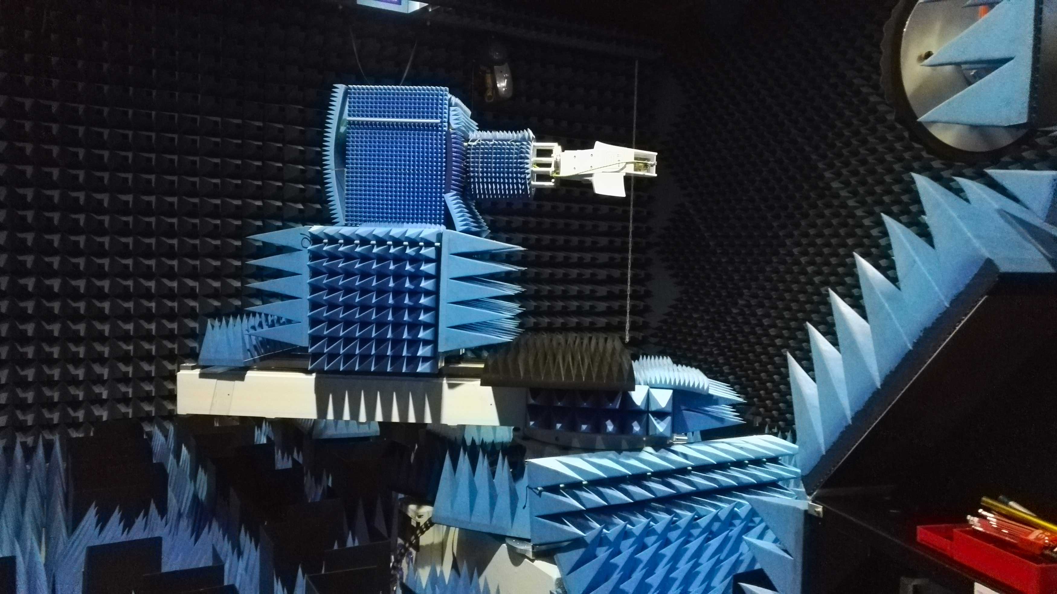 +
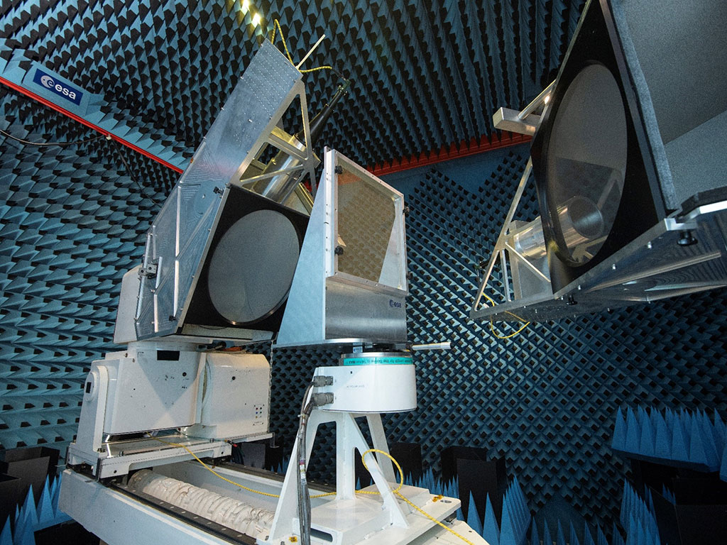
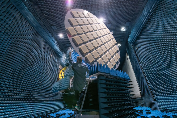
+CATR full view
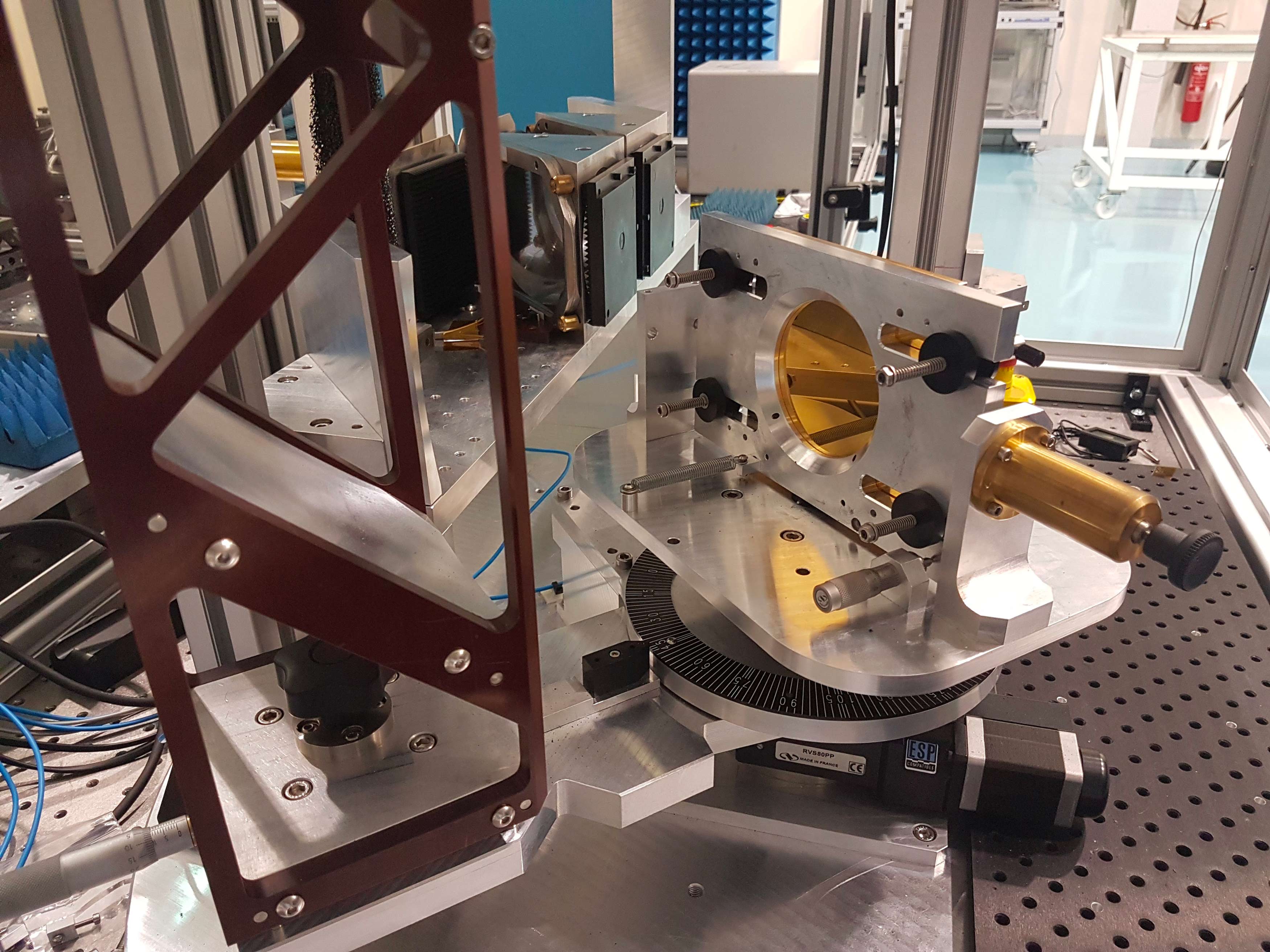 +
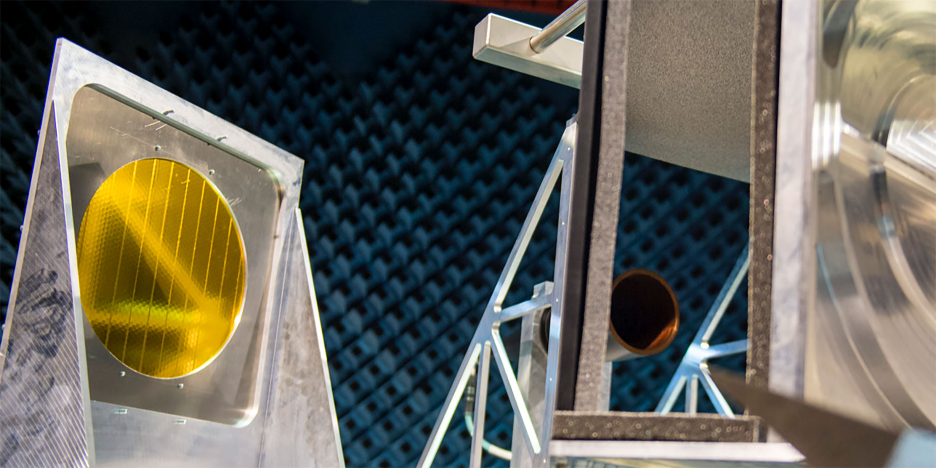
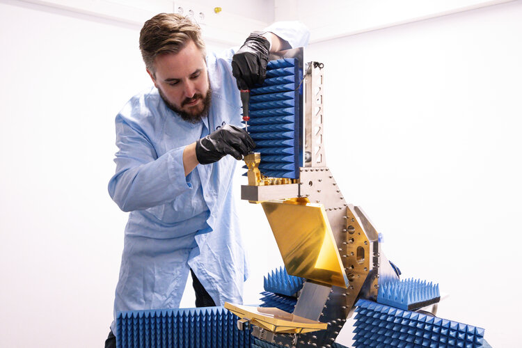
+CATR detail
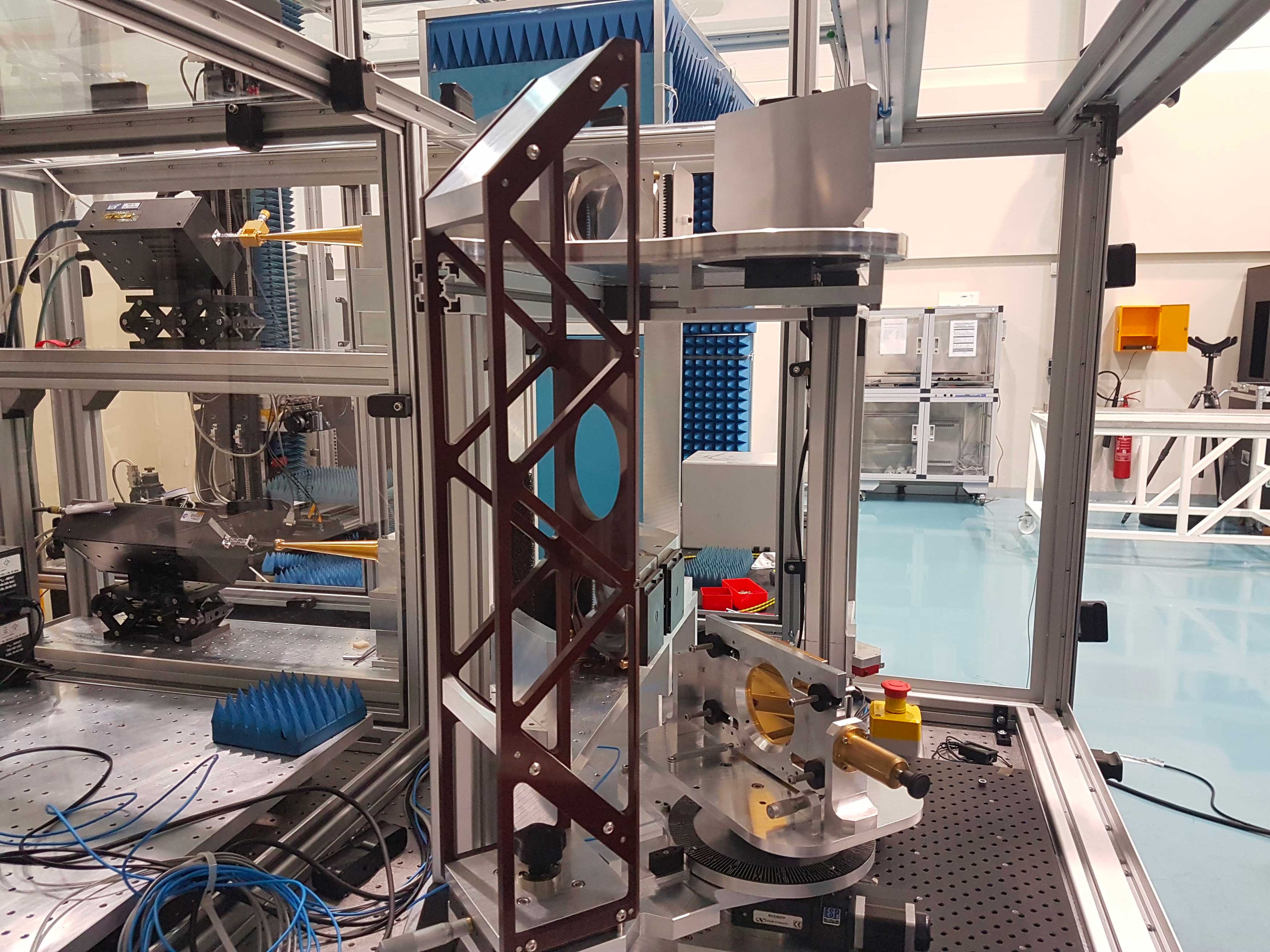 +
+CATR other detail
Services
Testing
- Antenna pattern, Gain and Efficiency
- EIRP, Total radiater power, Antenna Losses
- Radiated group delay, 3D Phase centre
- Antenna & Spacecraft EM interaction
- Return Loss and Antenna Coupling
- End-to-End Radiated payload performance
- Material reflectivity losses and Dieletric proprieties
- RF scattering testing
- Antenna Diagnostic
Measurements
- Prototyping
- RF characterisation
- End-To-End Performance
- Antenna Gain and Pattern measurement
- Radiated Payload End-to-End performance
Simulation
- Modelling
- RF Simulations
- Antenna-Satellite interaction
- Near Field to Far Field transformation
- Surface Currents Re-construction
- Diagnostics from measurements
Analysis
- Antenna Testing & Measurement Uncertainty Analysis
Technical Expertise
- Consultancy
- Training
- Ad hoc Auditing
- Development of Space Standards

WE CAN HELP YOU GET THE BEST OUT OF OUR LABORATORIES
FOR FURTHER INFORMATION REGARDING THE ACCESS TO THE LABORATORY
Contact us via Email
