Materials & Electrical Components Laboratory
Made up of more than 20 dedicated experimental facilities and hundreds of instruments overall, the Materials & Electrical Components Laboratory guarantees an optimal choice of electrical components, materials and processes for ESA missions and external projects. The capabilities of the lab consider the unique environmental challenges involved in building for space, and, additionally, investigating failures to ensure that similar issues do not occur on future missions.
The laboratory enables testing, analysis and measurement of space materials and EEE components to determine their suitability for space flight applications, by evaluating the effects of the space environment. Here, all of the unique environmental challenges involved in building for space are considered and failures investigated, to ensure issues do not occur on future missions. The team routinely assesses EEE components and manufacturing processes, and characterises all physical and chemical properties of the involved materials. It verifies and qualifies their use and investigates the causes of failures, providing impartial and independent testing, expert knowledge. This is achieved using the unique equipment support service only made possible at ESA-ESTEC.
The laboratory, with its team of highly trained engineers, is ISO 9001 certified, and its Co-60 radiation facility is accredited to ISO/IEC 17025. Additionally, it serves as a certification authority for space materials and processes (M&P) in Europe.
The Materials and Electrical Components Laboratory invites projects from all backgrounds to conduct non-routine work using our confidential and impartial services and products.
For testing requests, access to lab facilities, training and consultancy services, please refer to:

Optimal choice of electrical components, materials and processes for ESA missions and external projects
Expertise for performing test, analysis and measurement of space materials
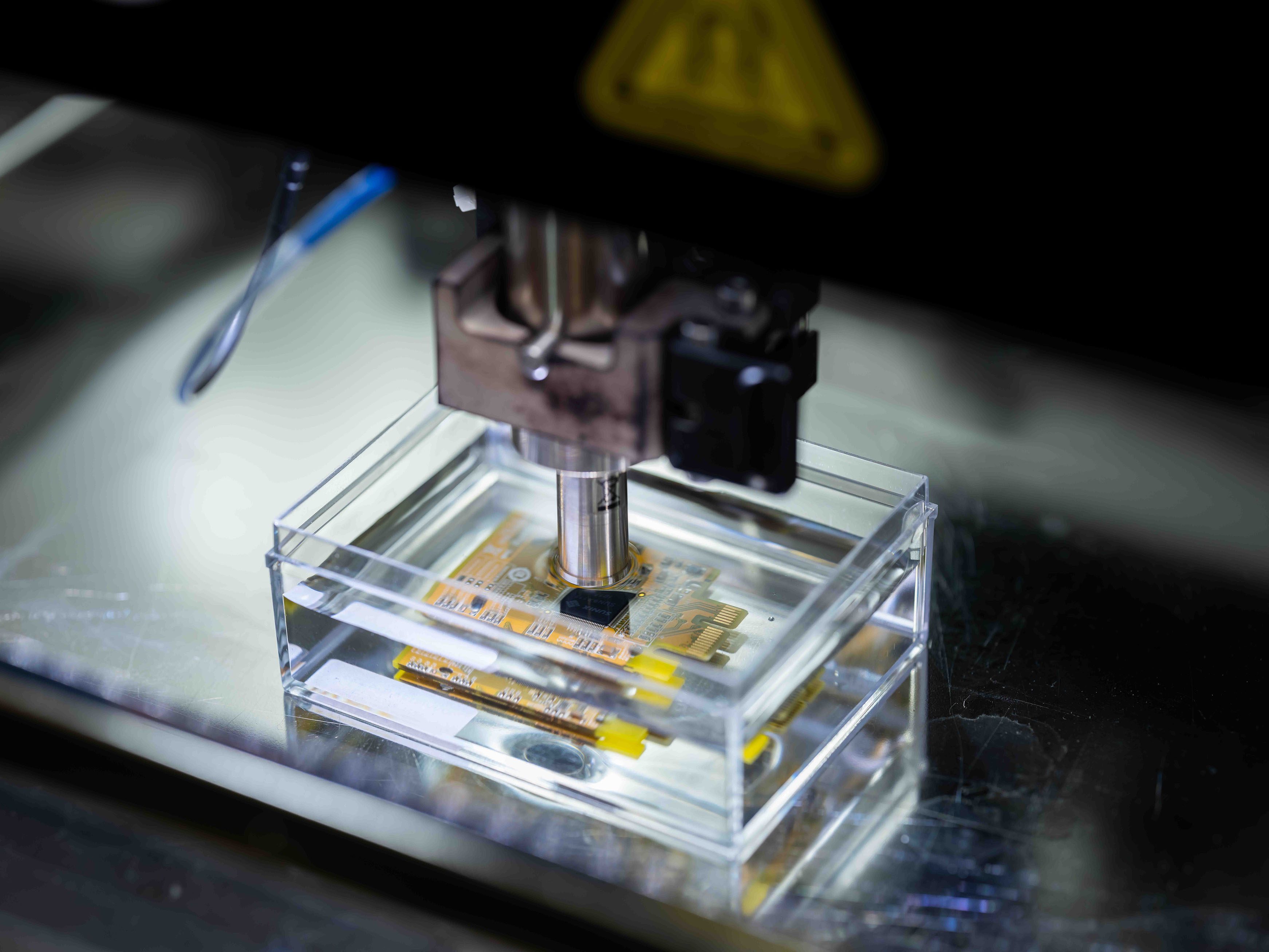 +
+Electronic component analysis. Credit: Remedia
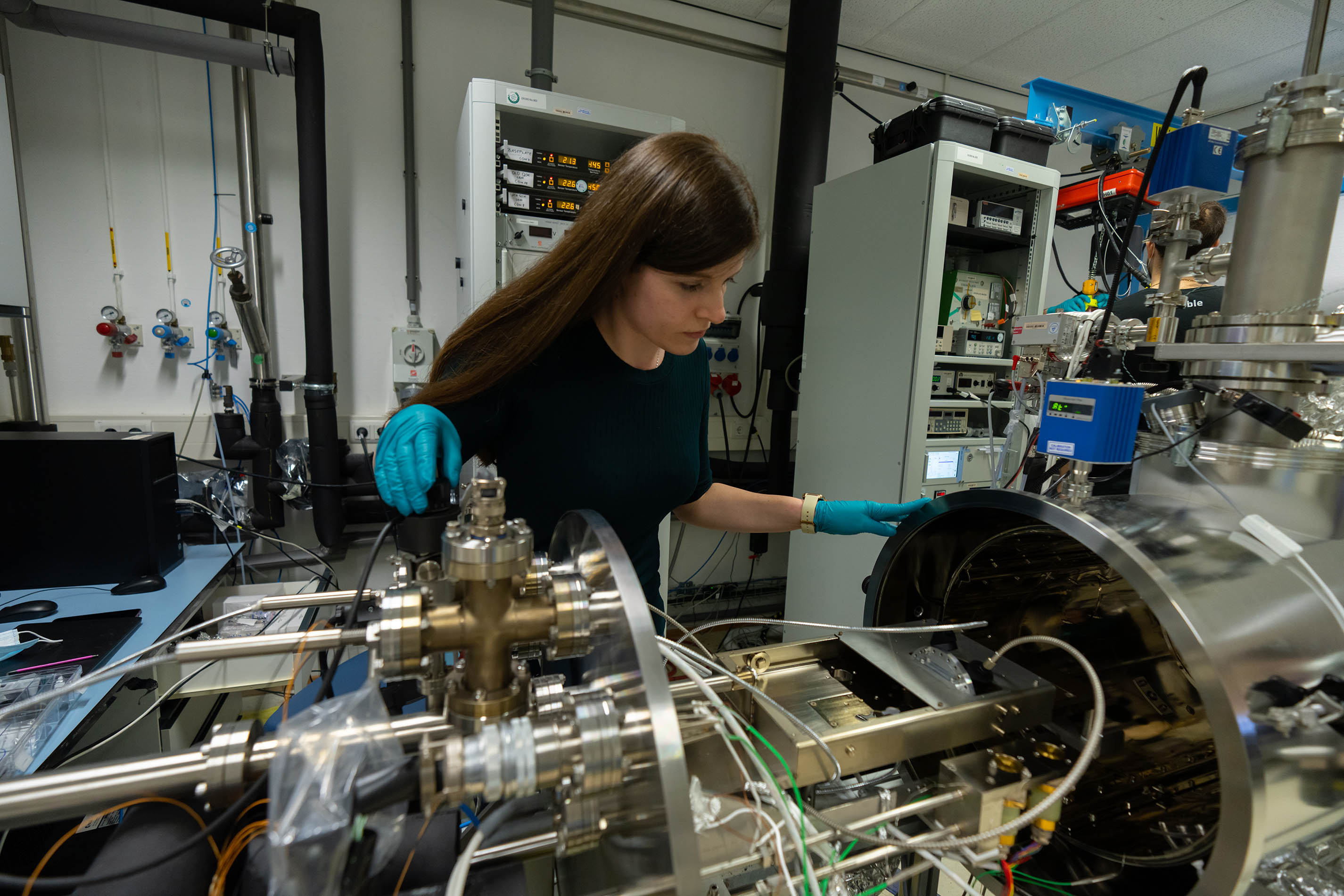 +
+Preparing for optical characterization of space materials in the Yuta facility. Credit: Remedia
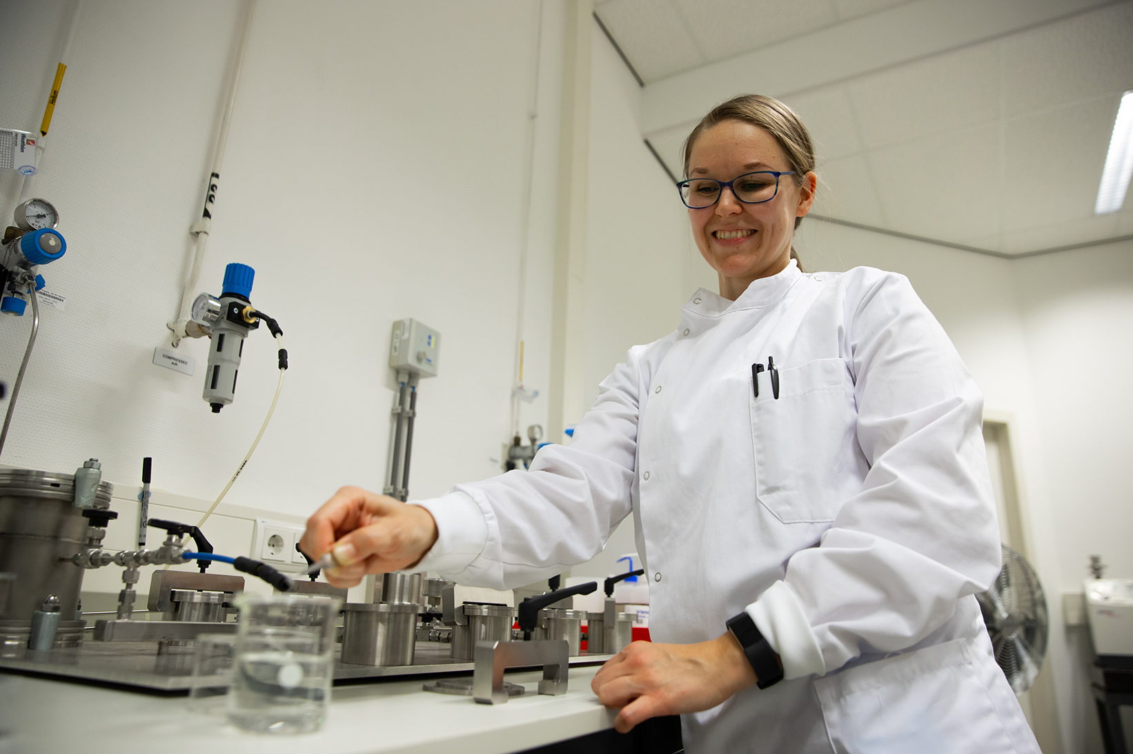 +
+Fine and Gross leak testing of electronic components. Credit: Remedia
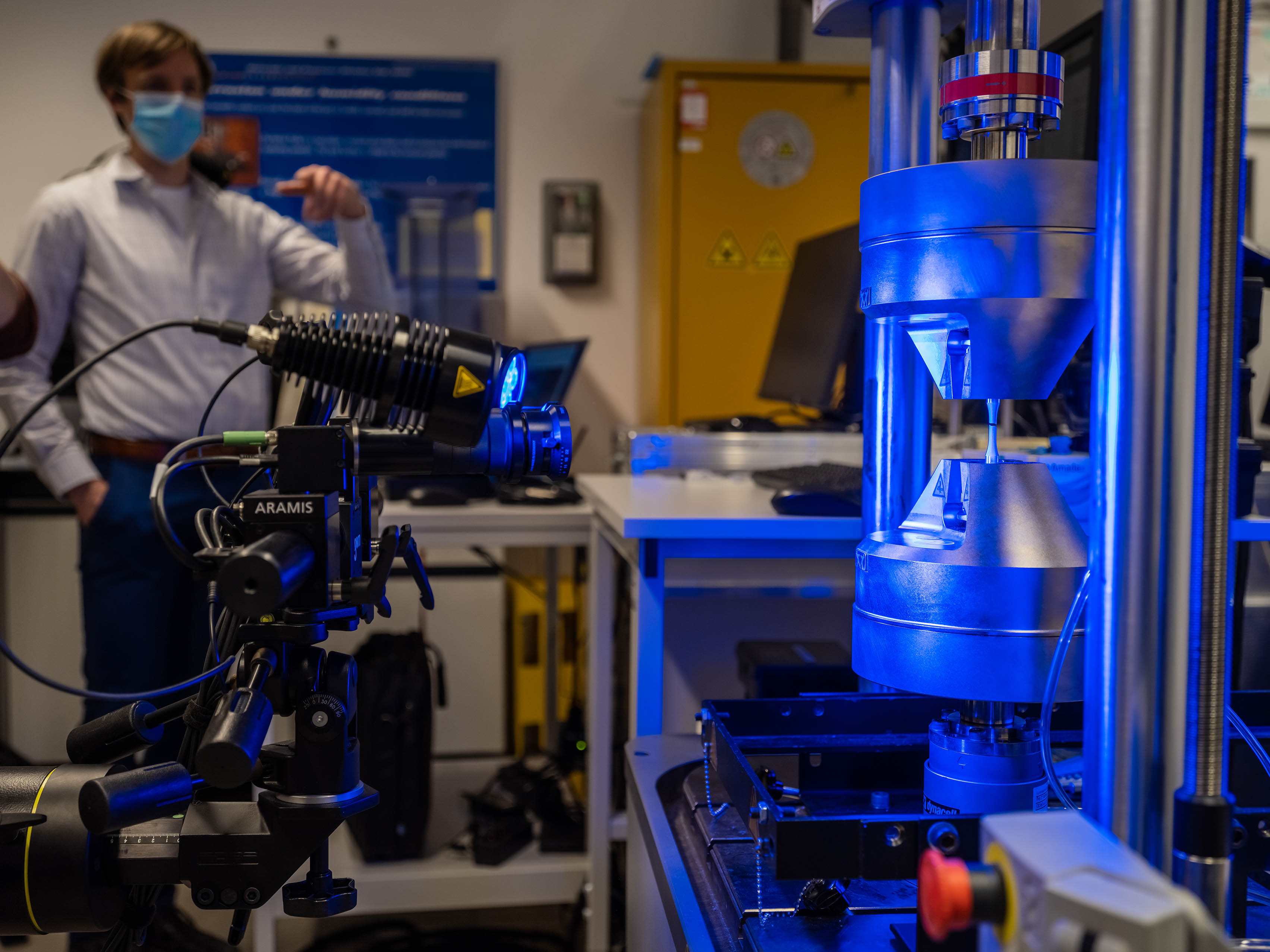 +
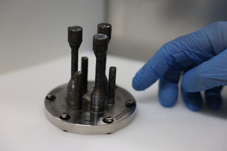
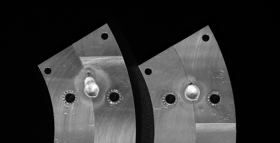
+Fatigue characterisation of materials. Credit: Remedia
1. ENVIRONMENTAL TEST LABORATORY
Contact: TEC-QEE.QMS.team@esa.int
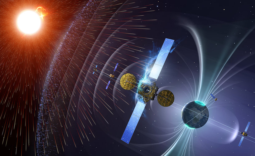
Over their lifetime, materials, components or small assemblies must withstand different environments without decreasing performance or experiencing degradation. In particular, in orbit, parts are subject to many potentially damaging factors, including UV radiation , X-rays, charged particles and orbital debris strikes. Frequent switching from scorching sunlight into bittercold shadow –thermal cycling- must be withstood, while atomic oxygen found at the top of atmosphere is inherently erosive/corrosive.
In some cases the synergistic impact of combined environmental effects has unpredictable consequences. The environmental test laboratory uses unique test facilities to replicate one or more detrimental factors of the space environment, including dedicated facilities for synergistic testing. For long-duration missions lifetime testing may not be practical, so facilities are also set up for accelerated testing to extrapolate results.
2. CLEANLINESS AND CONTAMINATION CONTROL
Contact: TEC-QEE.QMS.team@esa.int
Space hardware must be kept rigorously clean: any contamination could endanger instrument performance, mission success or astronaut health. Organic materials give off trace chemicals which, in the vacuum of space, can cause molecular deposition and even the thinnest of layers may affect contamination sensitive equipment such as telescope mirrors or laser lenses, solar array or thermal control surfaces. In enclosed pressurised environments , airborne contamination is the concern, as astronauts must not be exposed to toxic substances. Contamination by dust and debris - even sloughed-off skin cells- may cause beam scattering or affect the working of propulsion or mechanical devices. The Material's Physics and Chemistry Laboratory offers expert advice on cleanliness and contamination control, quantifies particulate & molecular contamination levels, audits cleanroom facilities tests materials, flight hardware for their contamination potential and performs bake-outs.
The laboratory is a unique collection of specially-designed facilities.
3. EEE COMPONENTS
Contact: EEELab@esa.int
The Materials and Electrical Components Laboratory maintains numerous facilities to carry out various analyses and tests to ensure reliable EEE Components (Electrical, Electronic and Electro-mechanical) on ESA missions and external projects. From the smallest passive EEE part to the most complex integrated circuit, the laboratory offers an outstanding testing capability. Recently, new capabilities for battery analysis have been added to the portfolio. The laboratory offers services in the areas of:
- Failure Analysis
- Destructive Physical Analysis
- Reliability Analysis
- Radiation Effect Characterisation
The laboratory focuses on tasks that are non-routine, are ESA project schedule critical, require independent and impartial support, and require specific confidentiality constraints.
The following facilities are employed to assess EEE Component reliability:
4. PHYSICO – CHEMICAL ANALYTICAL SERVICES
Contact: TEC-QEE.QMS.team@esa.int
The laboratory has a unique collection of state-of-the-art analytical measurement equipment to evaluate the physical, chemical and surface properties of test items: From thermo-optical characterization (emittance, reflectance, absorptance), to determination of molecular and lattice structure, passing through an exhaustive study of surfaces and topologies, and other material properties.
5. THERMAL ANALYSIS LABORATORY
Contact: TEC-QEE.QMS.team@esa.int
The thermal analysis laboratory in ESTEC has an exhaustive collection of instruments suited to characterize physical and chemical properties of samples at material level in a wide range of temperatures. From the well-known TGA and DSC techniques, commonly used to determine degradation and transition temperatures, curing levels or other possible chemical effects, to more dedicated techniques such as the rheometer which we use, amongst others, to characterize dynamic moduli under different temperature and humidity levels of viscous and solid samples. Furthermore, physical properties such as coefficient of thermal expansion, thermal conductivity and diffusivity, or electrical conductivity can be measured at sample level, providing useful values to modelling suites.
6. FACILITY PROTOTYPING
The Materials and Electrical Components Laboratory has the capabilities to construct prototype facilities in short timeframes, in response to project needs for rapid failure analysis and urgent investigations
We have experts in a wide range of disciplines, including :
- Vacuum engineering
- Facility design and manufacture
- Measurement and test techniques
- In-situ monitoring (optical, contamination, spectroscopy)
- Optical detection and measurement (UV, VIS, IR)
- UV light sources and intensity measurement
- High temperature test facilities
- Thermal control
- Contamination monitoring
We work closely with ESTEC infrastructure and the internal workshops, together with local suppliers. Facilities can be constructed on a modular basis, with a wide range of auxiliary hardware available, including :
- Vacuum equipment
- Thermal baths
- IR and optical cameras
- Quartz microbalances
- Temperature control equipment
- Sample plates
- Optical windows
- Electrical measurement
7. Materials and Processes
The laboratory has a wide variety of materials characterisation equipment, connecting in many cases microscopic characteristics to macroscopic properties.
SERVICES
Testing
- Vibration
- Shock
- Performance evaluation
- Life testing
- Environmental Testing
- Anomaly investigations
- Characterisation
- Radiation testing
- Cleanliness/contamination control
- PCB technology and electronic assembly verification
Measurements
- Dosimetry
- Prototyping
- Advanced metrology
- Materials physical and chemical characterisation, materials properties measurements in space simulated env., outgassing, vapour pressure, microscopy, spectrometry, gas chromatography
- Contactless strain measurements, X-ray internal defect measurements, 3D surface scanning
Technical expertise
- Consultancy
- Training
- Ad hoc auditing
- Development of Space Standards
- Cleanroom inspections
Analysis
- Thermal-mechanical analysis for materials, failure analysis, vepour pressure, outgassing, spectroscopic analysis
- Failure Analysis, fractography, generation of experimental data for static, dynamic mechanical, and thermal analysis
Simulation
- Modelling
- Virtual simulation
- Computational chemistry, thin film modelling, outgassing


WE CAN HELP YOU GET THE BEST OUT OF OUR LABORATORIES
FOR FURTHER INFORMATION REGARDING THE ACCESS TO THE LABORATORY
Please contact TEC-QEE.QMS.team@esa.int